
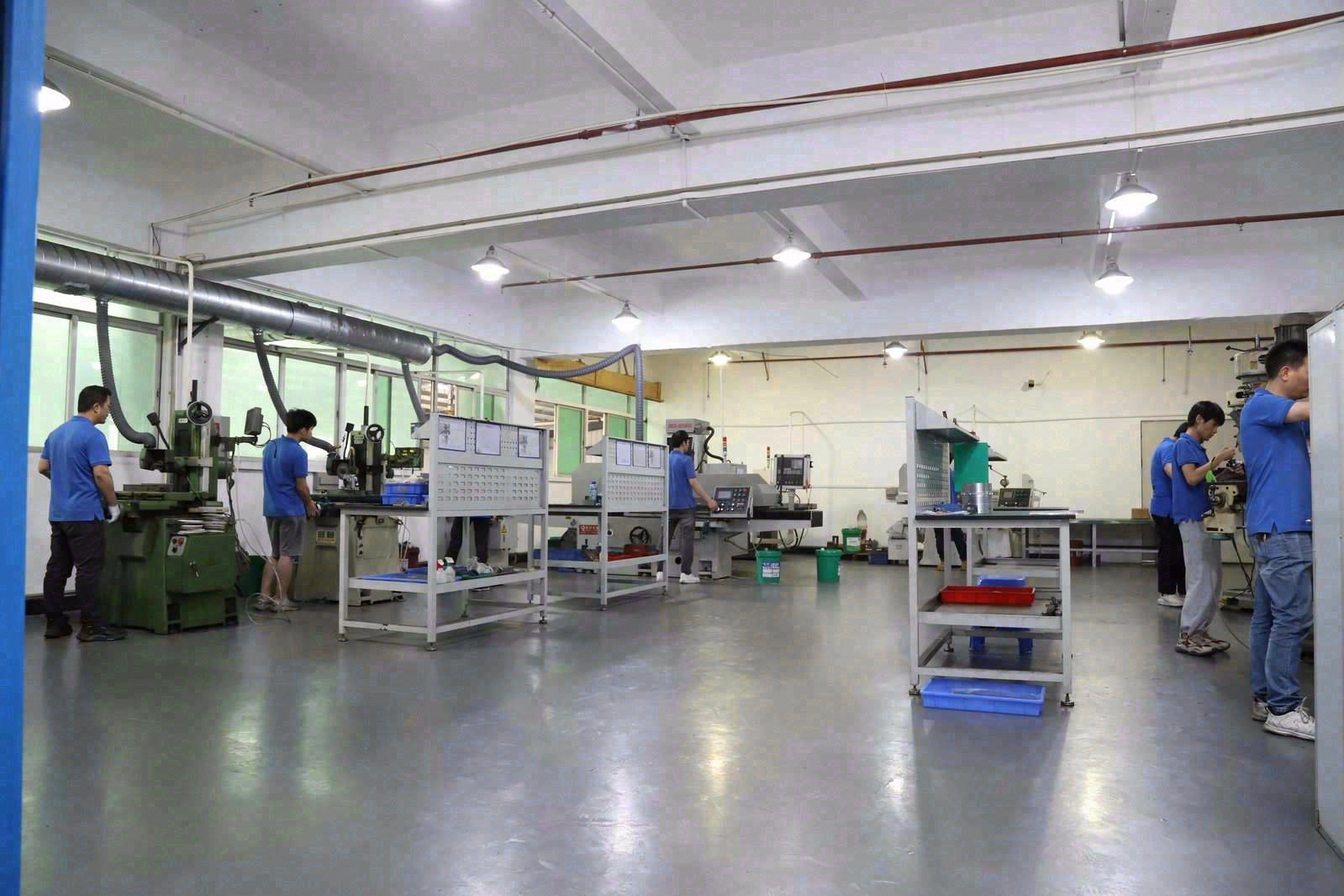
A mechanical component drawing is written in a shorthand that assumes the reader knows the conventions: the fit between a shaft and its bore, the hardness callout that survives heat treatment, the surface symbol with its lay direction and its machining method. The shorthand is efficient when both sides read it the same way, and expensive when they do not. This guide decodes the tolerance and finish conventions that mechanical components actually rely on — the mating fits, the hardness and heat-treat notes, the texture symbols and the drawing habits that decide whether a component fits its neighbor, survives its load and wears the way the designer intended.
Why do mechanical components need their own tolerance reading?
Mechanical components are defined by their relationships: the shaft fits the bore, the flange bolts to its neighbor, the pin locates the link. The tolerance on a mechanical component is therefore less about the component in isolation and more about the fit it must make with the parts around it, and the drawing expresses that fit through conventions that carry meaning beyond the numbers. A fit designation, a hardness range or a surface symbol is a shorthand the whole industry reads the same way, or is supposed to. The buyer who knows what the conventions mean can check whether the drawing expresses the intent, and the supplier who machines to the conventions can produce a component that behaves as the fit requires rather than as the numbers happen to allow.
The conventions matter because they carry the load that plain numbers cannot. A ± dimension says how big or small a feature may be; it does not say whether the feature must be round within that size, or flat, or true to its axis. A surface finish number says how smooth a surface is on average; it does not say which direction the tool marks run or whether the surface was machined or ground. The mechanical component drawing fills those gaps with geometric controls, surface symbols and process notes, and a drawing that relies on the shorthand without writing the conventions is a drawing that has left its meaning to the reader's assumption. The tolerance reading of a mechanical component is the reading of its conventions, and the buyer who can read them is the buyer who can check whether the drawing says what the assembly needs.
How do mating fits behave on a mechanical component drawing?
The fit between two mating features — a shaft in a bore, a pin in a hole, a slider in its guide — is the component's most important relationship, and the drawing expresses it through the size tolerances on each side. A clearance fit lets the parts move freely with a designed gap; a transition fit allows a small overlap or a small clearance; an interference fit holds the parts together by the grip of the metal itself. Ask which features of the component are mating fits and what each fit must do — move, locate or hold — because the size tolerance on each feature is chosen to produce the fit, and a drawing that tolerances each feature independently without regard to the fit can produce an assembly that binds or rattles even though every part measured correctly. The fit is the relationship, and the tolerances are its two halves.
The capability question follows the fit: to hold a designed fit at volume, each mating feature must hold its size band with process capability behind it. The band a serious shop holds — ±0.003 mm on milled and turned features and ±0.002 mm on precision ground surfaces, with Ppk ≥ 1.67 at the initial study on key characteristics and Cpk ≥ 1.33 on general characteristics. Capability is reported per characteristic: every report names the feature, its tolerance band, the sample size, the sigma method, and the study window. — is the room the fit is built in, and the supplier should state how it holds the mating features and how the capability is reported. Ask which features of your component are designated as the fit-critical ones and how the shop measures them — a bore by air gauge, a shaft by micrometer — because the measurement of a mating feature is the measurement of half a fit. A component whose fit features are measured and capable is a component whose assembly will fit every time; one whose fit features are cut and hoped for is a component whose assembly will fit sometimes.
What do hardness and heat-treatment callouts require from the drawing?
Many mechanical components earn their function from hardness, and the hardness is produced by a treatment that the drawing must express correctly. A case-hardened component has a hard surface and a tough core, and the drawing should state the case depth and the hardness range; a through-hardened component has a uniform hardness, and the drawing should state the range and the treatment; a component that is hardened after machining and then finish-ground must carry the process sequence on the drawing, because the final size is cut after the treatment and the pre-treatment geometry must allow for the movement. Ask which surfaces of the component carry the hardness requirement and whether the drawing names the depth, the range and the treatment. A hardness callout without its case depth, or a treatment sequence without its allowance, is a requirement that the shop will interpret, and the interpretation is where components fail under load.
The hardness and the finish interact on the surfaces that do the work. A hard surface that must also seal or slide carries a finish requirement that grinding must produce after the hardening, and the drawing should name the finish and the method together. Ask how the shop sequences the grind against the treatment and how it verifies the result — the hardness test on the surface, the case depth on a sample, the finish reading on the ground feature. The supplier that treats hardness as part of the process plan, with the sequence, the verification and the certificate stated, is a supplier whose components carry their hardness honestly; one that treats the callout as a note on the drawing is a supplier whose components will carry whatever the heat-treat house produced.
How do you read the surface finish symbols correctly?
The surface finish symbol on a mechanical drawing is a package of information, and reading it correctly means reading all of it. The number gives the roughness value — usually Ra in micrometres, with the understanding that Ra is an average and two very different surfaces can share one Ra. The symbol can also carry the machining method, the allowance and the lay — the direction of the tool marks — and those extras are often the information that matters. A seal face with its tool marks running radially versus tangentially behaves differently; a sliding surface with a lay against the motion wears differently than one with the lay along it. Ask which surfaces on the component carry finish requirements whose direction or method matters, and make sure the drawing states the lay where the function depends on it.
The finish range is as important as the number. A callout that says "Ra 1.6 maximum" is a one-sided requirement that any smoother surface satisfies; a callout that names a range — Ra 0.8 to 1.6 — protects the surfaces that need a controlled texture, like a seal seat that fails when it is too smooth to grip or a bearing surface that needs an oil-retaining texture. Ask whether the finish on the functional surfaces of your component needs a range rather than a maximum, and whether the drawing says so. A finish callout that carries a range is a finish requirement that has been thought about; one that carries only a maximum has left the lower bound to the machinist, and the lower bound is where the function often lives.
What do geometric controls add beyond the size tolerances?
Mechanical components rely on geometry as much as size, and the geometric controls are what make a flat face truly flat and a round feature truly round. Flatness controls the face that must seat evenly; parallelism controls the face that must align with its neighbor; perpendicularity controls the feature that must stand square to its datum; roundness and cylindricity control the feature that rotates or seals. Ask which surfaces of your component carry these controls and whether the drawing expresses them, because a face that measures within its size tolerance can still be bowed enough to break a seal, and a bore that is round on average can still be oval enough to wear its shaft. The geometric controls are the drawing's way of saying what the size tolerances cannot.
The relationship between the controls and the datums matters as much as the controls themselves. A position or parallelism callout is only meaningful against the datum it references, and the datum structure should reflect how the component is located in its assembly. Ask whether the drawing's datum structure matches the component's real mounting — the face it sits on, the bore it centers on — because a control measured against the wrong datum verifies the wrong relationship. A component whose geometric controls are drawn against the datums the assembly actually uses is a component whose geometry is verified the way the assembly experiences it; one whose controls reference a convenient shop datum is a component whose drawing and whose assembly disagree.
What belongs in the general tolerance block and the notes?
The general tolerance block is the drawing's default: the tolerances that apply to every dimension not specifically controlled, and its values decide what the un-called-out features cost and how they fit. Ask what the general block assumes on your drawing — the linear tolerances, the angular tolerances, the default radii — and whether the block matches the component's role. A general block that is tighter than the function needs prices the whole component for precision no feature earns; one that is looser than the fit needs lets the un-called-out features drift into interference. The general block is the drawing's background noise, and the buyer who sets it deliberately is the buyer who has priced the component's defaults as well as its callouts.
The notes block carries the requirements that no symbol expresses: the deburr condition, the edge break, the protection against corrosion between machining and assembly, the packaging, the marking. Ask what the notes on your drawing say and what they leave silent, because a component with no edge note is a component whose edges arrive as the machinist left them, and a component with no protection note is a component whose finish begins degrading at the machine. The notes are the drawing's memory for everything the symbols cannot carry, and a mechanical component drawing whose notes are complete is a drawing whose component arrives with its edges broken, its surfaces protected and its identity marked — the small things that make a component fit for assembly.
What tolerance and finish capability should the drawing expect?
The capability expectations should be written into the component's quality story as plainly as the geometry: ±0.003 mm on milled and turned features and ±0.002 mm on precision ground surfaces, with process capability of Ppk ≥ 1.67 at the initial study on key characteristics at volume. Ask how the component's fit features, geometric controls and finish ranges are verified against that capability, which are measured 100%, which by sampling, and what the report carries. The quality baseline of the supplier — ISO 9001:2015, with IATF 16949:2016 (product design excluded) and ISO 14001:2015 alongside where it serves regulated programs — is the frame that makes the numbers repeatable, and the certificate numbers and scope should be verifiable through the registrar. A mechanical component whose tolerance and finish expectations are backed by a stated capability and a verifiable quality system is a component whose drawing promises are supported by a process; one whose expectations float without a process frame is a component whose drawing is a wish list.
Ask how the shop would demonstrate the capability on the component's key features across a production run, and what the first-article report would carry for the fit and the finish. The evidence chain — the drawing callouts, the process capability, the inspection report and the certificate — is what makes a mechanical component's tolerance and finish real rather than asserted. A supplier that can show you the evidence chain before the order is a supplier whose components will arrive with their numbers attached; one that can describe the geometry but not the evidence is a supplier whose components will arrive with the numbers still to be produced.
Which drawing habits should be fixed before a mechanical component is quoted?
Fix the drawing when the mating fits are not expressed — when the shaft and the bore each carry an independent tolerance and no one can say what fit the assembly will get. Add the hardness and heat-treat information when a component must survive load and the drawing says only "harden." Write the surface ranges where a seal or a bearing needs a controlled texture, and the lay where the tool-mark direction matters. Add the geometric controls against the datums the assembly uses, set the general block to the component's real needs, and fill the notes with the edge, protection and marking requirements. A mechanical component drawing that carries its conventions completely is a drawing two suppliers will read the same way and machine to the same result.
Test the reading with the first article and its report: measure the mating features and check the fit they produce, verify the hardness on the load-bearing surfaces, read the finish on the sealing and sliding faces and check the geometric controls against the assembly's datums. If the first article behaves as the drawing promised — the fit is right, the hardness is in range, the finishes sit where the function needs them — the drawing's conventions have been read correctly and the component can be ordered with confidence. If a feature arrives that the drawing never really specified, the gap is now visible, and the next revision will write the convention that the first drawing only implied.
Frequently Asked Questions
Why do mechanical components need their own tolerance reading?
Because they are defined by their relationships — the fit, the alignment, the surface against its neighbor — and the drawing expresses those relationships through conventions: fit choices, hardness ranges, surface symbols. Reading the conventions is reading the component.
How do mating fits appear on a component drawing?
Through the size tolerances on each side of the fit, chosen together to produce the designed clearance, transition or interference. Each feature should hold its band with capability so the fit holds at volume, with the mating features measured by the right instruments.
What does a hardness callout need to be complete?
The range and, for case hardening, the depth, plus the treatment sequence against the machining — hardened after machining then finished by grinding needs an allowance for movement. A hardness callout without its depth and sequence is a requirement the shop will interpret.
What is the lay on a surface finish symbol?
The direction of the tool marks, which can matter to function: a seal face or a sliding surface behaves differently with the lay along or across the motion. Where the direction matters, the drawing should state it rather than leave it to the machinist.
What tolerance and capability should a mechanical component carry?
±0.003 mm on milled and turned features and ±0.002 mm on precision ground surfaces, with Ppk ≥ 1.67 at the initial study on key characteristics and Cpk ≥ 1.33 on general characteristics. Capability is reported per characteristic: every report names the feature, its tolerance band, the sample size, the sigma method, and the study window. — with the geometric controls and finish ranges verified against the datums the assembly uses.
What do geometric controls add beyond size tolerances?
Flatness, parallelism, perpendicularity and roundness control the shape and the relationships that size alone cannot. A face can measure within its size and still be bowed; a bore can be round on average and still be oval. The controls make the geometry explicit.
How do I know a mechanical drawing is complete?
When the mating fits are expressed, the hardness and treatment are named with their sequence, the functional finishes carry ranges and lays, the geometric controls reference the assembly's datums and the notes cover edges, protection and marking. Then two suppliers will read it the same way.
Reading a mechanical drawing and want the conventions confirmed before machining?
Send the drawing to [email protected] or call +86 13126536955 and ask which fits, hardness notes and surface symbols would be questioned. See the quality page for the inspection framework and the services page for the treatment and finish scope.